After you have determined the size of fuel tank you need for a diesel fire pump, what are the general requirements for installation? Assuming that you are under under the International Building/Fire Codes, you would go through the following chain of code references: IFC (2021 edition) 5701.2 Nonapplicability. This chapter shall not apply to liquids as otherwise provided in other laws or regulations or chapters of this code, including: ... (4) Storage and use of fuel oil in tanks and containers connected to oil-burning equipment. Such storage and use shall be in accordance with Section 605. For abandonment of fuel oil tanks, this chapter applies.. IFC (2021 edition) 605.1 General. The design, construction, installation, operation, alteration, repair and maintenance of nonportable gas-fired appliances and systems shall comply with the provisions of this section and the International Fuel Gas Code. The design, construction, installation, operation, alter...
Fire pump sizing is not like commercial pump sizing. We don't care about efficiency, and you order pumps in only specific sizes. This article touches upon some items to consider when picking a fire pump.
In general, the first step is determining your system demand point. Discussion of how exactly you determine this is beyond the scope of this article and has a lot of nuance depending upon your site-specific needs. However, for simplicity let's assume that you have a dry-system in an attic with a demand point of 305 gpm (2535 sq ft x 0.10 gpm/sq ft x 1.20 overflow/imbalance factor).

Check out AC Fire's online pump selector at https://www.selectacfirepump.com/ and play around with some selections, or reach out to us at sales@anvil-fire.com for support on your projects in the NorthWest.
In general, the first step is determining your system demand point. Discussion of how exactly you determine this is beyond the scope of this article and has a lot of nuance depending upon your site-specific needs. However, for simplicity let's assume that you have a dry-system in an attic with a demand point of 305 gpm (2535 sq ft x 0.10 gpm/sq ft x 1.20 overflow/imbalance factor).
Rated Flow (gpm) Sizing
The first item you must specify is the pump flow rate. Per NFPA 20 (2013 edition) table 4.8.2 pumps are only allowed to be listed with the following flow rates in gpm:- 25, 50, 100, 150, 200, 250, 300, 400, 450, 500, 750, 1000, 1250, 1500, 2000, 2500, 3000, 3500, 4000, 4500, 5000
So with our example demand of 305 gpm, would you go with a 300 or 400 gpm rated fire pump?
While manufacturer's pump curves go way beyond the ratings above, NFPA 20 section 4.8.1 only allows you to use a fire pump out to 150% of its rated capacity. That means that a 300 gpm pump can be run out to 400 gpm (300 x 1.5) and could easily meet the example demand flow rate. One could even use a 250 gpm pump with the corresponding max flow rate of 375 gpm (see the bottom of this article for additional discussion).
The other common condition is a standpipe. Assume you have two stair-towers and total demand of 750 gpm. Should you run a 500 gpm out 150% to 750 gpm? In our opinion that is probably a poor choice since you are so close to the 150% limitation.
So what is the harm in just selecting the next pump size up (i.e. 400 gpm for our 305 gpm example demand)? First, can you water supply handle flowing at least the 100% and/or 150% flow rate? While technically NFPA 20 allows you complete testing at less than 150%, if you can avoid this situation it would be better.
Second, there may be some hidden cost. For example going from a 400 to 500 gpm pump also means you go from 4-inch suction to 6-inch suction (see our NFPA 20 pump pipe size look-up app at https://anvil-fire.com/apps_pump_sizing.html). In addition, you are generally probably increasing the horsepower and therefore the overall cost of the equipment. Or even causing an electrical transformer to be upgraded.
Note that FM Global only allows you to run the pump out to 140% of rated pressure per FM Global Data Sheet 3-7 (Fire Protection Pumps - Oct 2021 Revision) section 2.4.6.4.
Rated Pressure (psi) Sizing
The second item you must specify is the rated pressure you want. Manufacturers must list each pressure rating in order to maintain listing with UL and FM Global. On occasion you will find some holes in approved pressure ratings, but AC Fire has a long history and therefore an amazingly wide range of rated pumps to accommodate almost any demand.
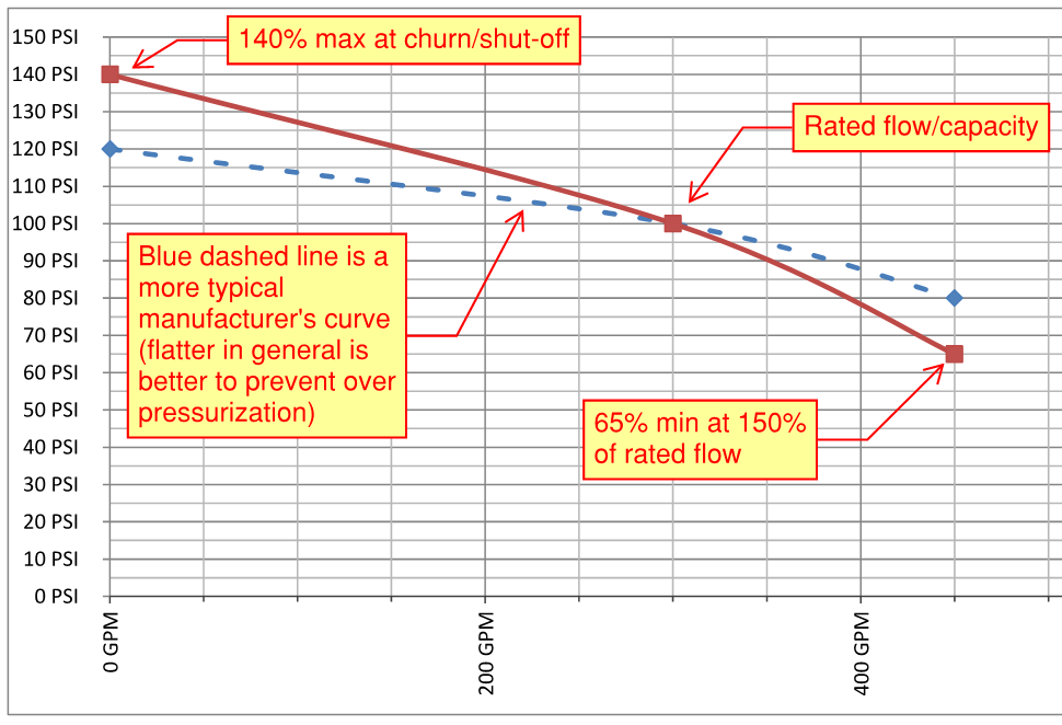
While not directly impacting your selection, it should be noted that NFPA limits manufacturers to how "steep" their curves can be in regard to pressure. See the curve below for the specifics. These limitations are a non-issue when you buy a listed pump as they have already had to comply with the limitations.
However, you should pay careful attention to the churn pressure (sometimes also called shut-off or dead-head pressure). When a fire pump is not flowing any water it produces the highest discharge pressure. In general most fire sprinkler components are listed to 175 psi.
Let's take the example of you have 50 psi static pressure from the city + our 100 psi rated pressure for a total 150 psi when flowing the 100% rated gpm. Sounds good, right? Maybe not if your churn pressure is 126 psi which is not unthinkable depending upon the specific pump selection (50 psi static + 126 psi churn = 176 psi). Always provide the max city pressure to your pump rep and look at the pump specific curve to ensure no surprises in the field.
In addition, make sure you check how much pressure you have at your desired flow rate from the city water supply. You can use the formula below or just use the quick calculator at https://anvil-fire.com/apps_log_graph.html

In addition, make sure you check how much pressure you have at your desired flow rate from the city water supply. You can use the formula below or just use the quick calculator at https://anvil-fire.com/apps_log_graph.html

Check out AC Fire's online pump selector at https://www.selectacfirepump.com/ and play around with some selections, or reach out to us at sales@anvil-fire.com for support on your projects in the NorthWest.
A quick reference chart for the 150% and 140% flows of the various pump ratings.
Additional FM Global Recommendations:
Not fully addressed in this article are the redundancy requirements recommended by FM Global. As a starting point, we would flag the following requirements from FM Global Data Sheet 3-7 (Fire Protection Pumps - Oct 2021 Revision):
2.4.6 Pump Sizing2.4.6.1 Size the pump to meet the maximum required flow and pressure demand for the system (Qmax).2.4.6.2 The standard water supply for pump and tank configurations are to be made of either one 100% Qmax pump or three (3) 50% of Qmax pumps. For non-storage occupancies, it is acceptable to use two (2) pumps of different driver types, electrical and diesel, equally sized, each meeting a minimum 75% of Qmax (for multiple pump installations, the characteristic pump curves should be identical).2.4.6.3 If flow and pressure demand cannot be provided by the standard water supply, use N-Number of pumps, equally sized (for multiple pump installations, the characteristic pump curves should be identical), to meet the maximum required flow and pressure demand (Qmax). However, N+1 Pumps need to be installed, preferably half electrically driven and half diesel driven.2.4.6.4 For centrifugal pumps, use a maximum of 140% of the pump rated flow capacity to meet the combined system demand and hose streams (if also supplied by the fire pump), if one 100% Qmax pump is used.2.4.6.5 For multiple centrifugal pumps, use a maximum of 110% of the pump rated flow capacity to meet the combined system demand and hose streams (if also supplied by the fire pump).2.4.6.6 Size the pump driver equal to or larger than the maximum peak power required by the pump at any point over its entire flow range. See Sections 2.4.19 and 2.5.1 for more information.2.4.6.7 Size a booster pump’s rated pressure based on the minimum anticipated suction pressure at the maximum required flow demand of the system. Review the daily and seasonal fluctuations in supply pressure to determine the minimum anticipated pump suction pressure.